
The function of Power Ruler mainly uses to design each kind of scale, turn on EzCad 2 and select “PowerRuler” in the laser menu.

Click “Power Ruler” the mark dialog box is shown in Figure:
New File: The software will close the documents which you are editing and meanwhile create a new file.
Open File: When click “Open”, the software will pop an open-file dialog to ask you to select the file you want to open.
Save File: save the current file to disk.
Save as: save the current file to disk by another name.
Export to WS: export the file to the software workspace.
Edit: Revision the content.
Delete: Delete the content.
Click “Add” presenting to edit the ruler, following the dialog box shown in Figure:

Type:
Line: The current parameter is the line parameter value.
Value: The current parameter is the value parameter value.
Text: The current parameter is the text parameter value.
VectorFile: The current parameter is the vectorfile parameter value.
Text:
Rotate: the angle of the text revolving.
Pen No.: This item indicates that objects with the selected pen number will be marked.
Graduation Num: The total graduation numbers need to be marked.
Start Graduation: Set the position of start marking graduation.
Increment pos: the space between two neighboring lines.
Line width: Set the width of the line.
Start point: Set the start point of the line.
End point: Set the end point of the line.
Start value: Set the start value of the line.
Inc. value: Set the Inc. value of the line.
Dot bit count: Set the dot bit count of the line.
0 not show tail zero: 0 did not show behind 0.
Text: show the text information on the ruler. We can see the figure when we select “Text”, We can compile the text content in the white frame.
Vector File: Show the information of the vector file on the ruler.
Scale X: width of the vector file.
Scale Y: height of the vector file.
Angle: the angles between a vector file and X axis.
For example: make a Straight ruler long thirty centimeters (three hundred millimeters ):
After set well the External Axis, select Straight ruler, click “Add” then the dialog box popup to set the Line.
Set the longest degree ten: There are thirty-one degree ten lines from zero to three hundred, from the start graduation of the workpiece, the space is ten millimeters, the length is seven millimeters, so as to the “Graduation Num” is thirty-one, “Start Graduation” is 0, “Increment pos” is ten, “Start point” is (zero, zero), “End point” is (zero, seven);
Set the degree five: There are thirty degrees five lines from zero to three hundred, from five millimeters of the start graduation, the space is ten millimeters, the length is five millimeters, so as to the “Graduation Num” is thirty, “Start Graduation” is five, “Increment pos” is ten, “Start point” is (zero, zero), “End point” is (zero, five);
Set the degree one: There are two hundred and forty degrees one line from zero to three hundred, in order to avoid degree ten and degree five superposition, degree one lines need to set four times: from one millimeter, two millimeters, three millimeters, four millimeters in turn, the space is five millimeters, the length is three millimeters, so as to the “Graduation Num” is sixty, “Start Graduation” is one, two, three, four in turn, “Increment pos” is five, “Start point” is (zero, zero), “End point” is (zero, three);
Set the Value: select “Value”, and only input the value of degree ten lines, so as to the “Graduation Num” is thirty-one, “Start Graduation” is zero, “Increment pos” is ten, “Start value” is zero, “Inc. value” is ten, “Start point” is (zero, zero), “End point” is (zero, eight);
Set the unit of the ruler: select “Text”, “Graduation Num” is one, input “Start Graduation” and “Start point” according to the actual situation, and input the text content which can show.
Now, the thirty-centimeter Straight ruler completed.
The method of making Ring ruler or Disk ruler: first, click “Param” the dialog box popup to set the External Axis.
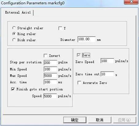
Straight ruler/Ring ruler/Disk ruler: The ruler’s type need to mark currently, choose is enabled.
Part diameter: The workpiece accurately diameter of the “Ring ruler” or “Disk ruler”.
Reverse: Reverse the moving direction of the expansion axis.
Pulses per round: The pulse number of the expansion axis motor makes a circle needed. We can count pulse number per revolution X through the following formula:
X = (360 / N) * n
X refers to the pulse number per round;
N is the pace angle of the electric motor;
n refers to the subdivision number of driver;
Minimum speed: The minimum speed of the expansion axis;
Maximum speed: The maximum speed of the expansion axis;
Accelerate time: The time of the expansion axis need when it moves from minimum speed to maximum speed.
Go to start position after finish: The expansion axis returns to the start position after finishing processing.
Speed: The speed of the axis going back to the initial position after finishing the marker.
Zero: Whether the current expansion axis has zero-switch input signal. Without zero signal, the software can’t build up absolute coordinates. Marking a set of parts, we need to make every mark at the same position. To mark the figure at the same position each time, the system takes the current expansion axis as a default original point before marking in the case of without zero signal. After processing a part, the system moves the axis to the original position automatically. In this way, each part will be marked in the same position.
If zero is enabled, zero switcher will be found automatically. The software creates an absolute coordinate after finding out zero switcher. If the system failed to find out zero switcher, the expansion axis cannot be used until the appointed time set by parameter zero time out has expired.
Speed of Goto Zero: The move speed when the expansion axis goes zero.
Accurate Zero: When it is selected, the axis must give three zero signals in the go zero process; if it isn’t selected, the axis only needs one signal.
Correct axis: The system will present “Zero time out” when failed to reach the position where the zero switcher was assembled within the appointed time.
Return “Power Ruler”, similar to the method of making straight ruler to complete the graphics.